What Is the Difference Between 2D, 2.5D, and 3D Contouring?
A CNC machine’s toolhead can move in multiple directions depending on the type of machine being used. Starting from two-dimensional cutouts, the complexity goes all the way up to 9-axis machining.
In CNC terminology, the spindle or router holds the toolhead that chips away at the workpiece. Like with a 3D printer, it can usually move in three dimensions: horizontally across the bed (x-axis), from front to back across the bed (y-axis), and perpendicularly moving up from the bed and plunging down into the bed (z-axis). By coding the toolpaths differently, various styles of CNC machining come to the surface, each with their own benefits and drawbacks.
For hobbyists and starting professionals, 2D, 2.5D, and 3D contouring are the most popular processes by far, with each one offering their own opportunities. Let’s dive in to learn about the main differences.
What Is 2D Contouring?

2D Contouring using the Profile Toolpath in Vectric software.
Two-dimensional CNC works as the name implies: the toolhead remains at the same depth during the entire milling process with no vertical movement. It is the machining equivalent to a laser, water jet, or wire cutter that also moves their end effector in directions X and Y alone. And similarly, 2D contouring is generally used for cutting and engraving.
2D CNC is driven by vectors with file formats such as Illustrator (AI), AutoCAD (DXF), EPS, PDF, and SVG. Modern CNC software such as PlanetCNC, Vectric, and FlashCut include several smart features for vector design work:
Direct DXF import
Automatic nesting algorithms to minimize material loss
Kerf compensation to ensure accurate cutouts
Bridging of internal cutouts
Corner looping to reduce dross on the edges of metalwork
Popular applications for 2D CNC machining are:
Promotional material – logos, signage, in-store displays
Home decoration – wall panels, number signs, cutting boards, seasonal items, photo engravings
Mechanical parts – gears, enclosure plates, aluminum frames
Electrical circuit boards (PCBs)
“Parametric design”-style furniture – 2D panels, each unique, form a 3D shape when assembled in line
What Is 2.5D Contouring?
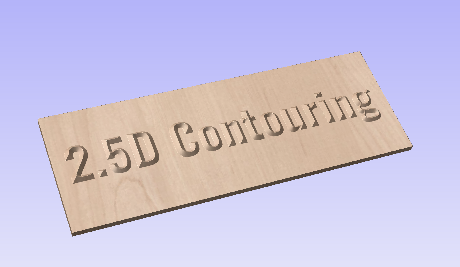
2.5D Contouring using the Prism Toolpath in Vectric software.
With 2.5D CNC, things become a little more complex. Here, the toolhead moves across the xy-plane in layers. That is, it cuts into the workpiece at a specific height, and when done with the layer, the toolhead moves a discrete step axially along the z-axis in order to start with the next layer.
It is the same procedure the nozzle on an extrusion-type 3D printer follows, except the CNC machine takes away material in a subtractive rather than additive way.
As such, a 2.5D CNC machine does not need a true z-axis but can do with a solenoid for discrete steps. The limitation is that all features of the workpiece come out flat at varying depths. Yet, by using different toolbits such as dado, V-groove, roundover, chamfer, and ogee form bits, non-flat features and interesting designs can be created.
Note that instead of the z-axis, one of the other axes can also be separated to have the toolhead move in layers along one direction of the table bed instead of vertically. And in water jet cutting, 2.5D means that the cutting head can tilt in angles up to 55 degrees for producing sloped surfaces.
Here is a selection of possible 2.5D CNC projects:
Engraved plaques, V-carving for memorial stones
Toys – puzzles, tabletop game boards, doll houses, voxel-type figurines, dominoes
Cabinetry, inlaid table tops
Pocketed items – storage boxes, instrument panels, wooden clocks, food trays, stepped bowls, catchalls, coasters, bathtub trays, lap desks, structural shells
Data visualization – graphic charts, topographic maps
What Is 3D Contouring?

3D Contouring using 3D modeling tools in Aspire software.
Most CNC machines in practice are three-dimensional cutters. That is, the toolhead can move along the x, y, and z axes simultaneously to permit double-curved surfaces.
Usually the cutter moves in a back and forth motion horizontally, known as rastering, with concurrent up and down action on the z-axis. Because three-dimensionality is mostly limited to the top surface of a workpiece, it is also known as relief machining. It uses dedicated end mills such as ball nose cutters for realizing ultra-smooth surfaces.
The added form complexity of 3D CNC machining is reflected in more complicated software programming and G-code files to store multi-axis continuous toolpaths.
Artificial intelligence is in development to optimize toolpaths for minimum machine time while retaining maximum part quality. As a CNC enthusiast you will need to invest time in learning full-fledged computer-aided manufacturing (CAM) and computer-aided design (CAD) software such as SolidWorks, Fusion 360, or ZBrush.
Common 3D file formats used for CNC manufacturing are Rhinoceros (3DM), sometimes with a Grasshopper plugin, 3ds Max (3DS), Lightwave (LWO), SketchUp (SKP), STL, OBJ, and AutoCAD (DXF).
Well-known 3D CNC applications are:
Complex mechanical parts – helical gears, wheel hubs, propeller and fan blades
Aluminum molds to send off to an injection molding service for series production
Relief sculptures in wood, stonework, or ice
Jewelry in aluminum or brass
Architectural models
Musical instruments
Sports equipment
Beyond 3D

4D Rotary axis using the rotary option in Vectric software.
Even though the scope of our discussion goes up to 3D CNC, it’s possible to work in four, five, or more axes. The workpiece is fixed up to the third dimension, but the fourth dimension includes a rotary table allowing the toolhead to work on different sides of the workpiece.
This makes 4D CNC technology suitable for a host of new utilizations such as artistic figurines, product prototypes, and scale models of concept vehicles.
And the cutter remains fixed in a vertical orientation in lower-dimensional CNC operations, with 5D machining the spindle can swivel to facilitate diagonal drilling, complex undercuts, and internal details. Alternatively, in a trunnion table setup a secondary rotary table is stacked together with the first for advanced opposing rotations. Machining here almost becomes freeform carving, with the intricacy of organic shapes nearing that of 3D printed geometry.
So-called indexed setups, or 3+1 and 3+2 machining, are forms of respectively four and five-dimensional CNC where the A and B rotations are locked in place first, and then the toolhead carves along the x, y, and z-directions, whereas with continuous 5-axis CNC milling everything happens in sync.
Even though 4D and 5D machines can require a significant upfront investment, for small companies it can still be worth looking into. Besides opening up new key applications, the cutting rate is significantly higher even for simple parts, saving time and ultimately returning the initial fixed costs.
Get Started Today
If you get your feet wet in the world of CNC, you will be amazed by the possibilities. With a creative mindset it can be a perfect tool for impressive projects, even when not stepping beyond 2.5D.
At this level, the beginner or hobbyist will find that excellent software is available, such as Vectric, that incorporates all kinds of smart features to streamline the design-for-CNC process. Don’t hesitate to take the plunge along the z-axis for true three-dimensional work and take your skills to the next level.